I haven’t been actively maintaining my blog these days. I recently moved to the Buffalo, New York area and settling down. I am willing to keep up with my blog posts. I have some great news to share with my readers.
My brother and I are going to be exhibiting at the World Maker Faire on September 23rd and 24th, 2017 in New York City. We are going to be showing off a DIY Personal Health Dashboard. We have been working on a visual aid that motivates one to stay physically active.
I plan to share my progress of our dashboard through the different stages.
I must admit that I have not been actively maintaining my blog. I am taking another stab at regularly blogging.
I am going to start with some great news my brother and I received earlier this week. We built a series of open source hardware including a personal health dashboard (pic below), a contact thermometer etc. and presented it at conference.
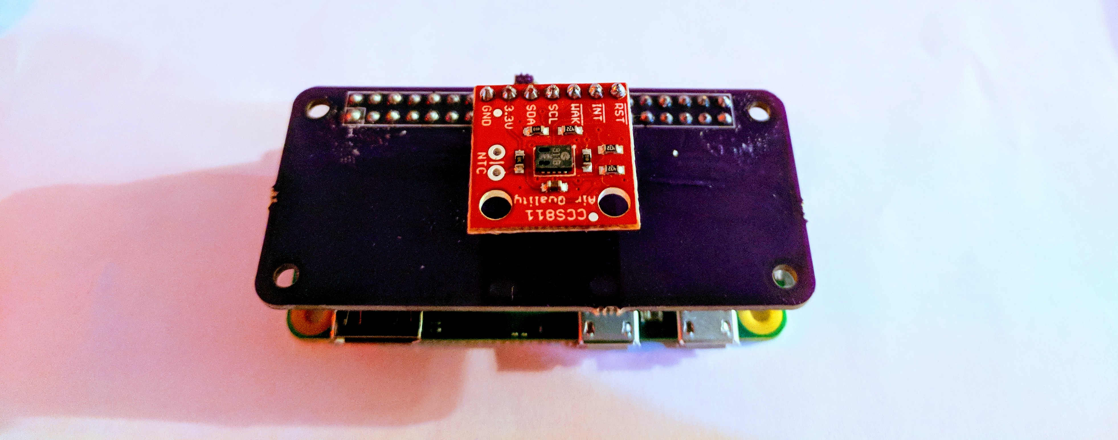
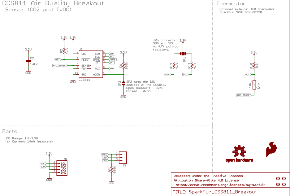
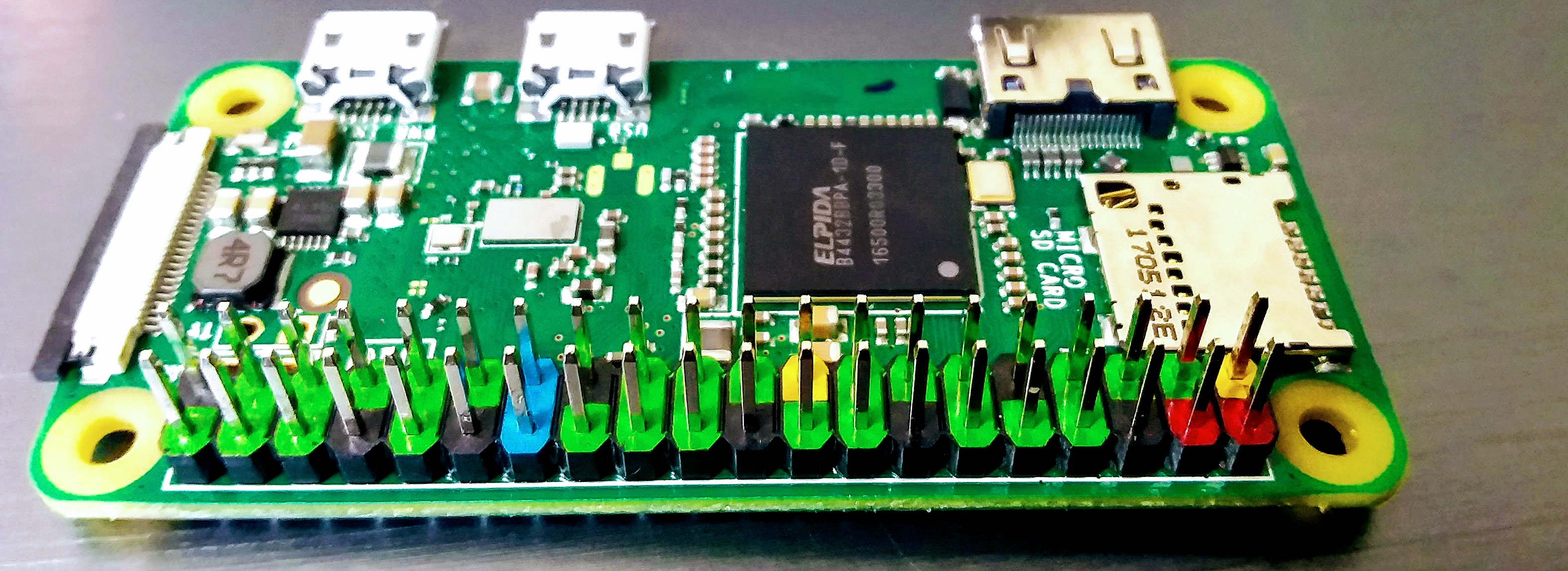
I designed an add-on board for my Raspberry Pi Zero to interface a CCS811 volatile organic compound sensor (Source files available from here). The CCS811 comes with an I²C interface.
Raspberry Pi Zero add-on board for Sparkfun’s CCS811 breakout
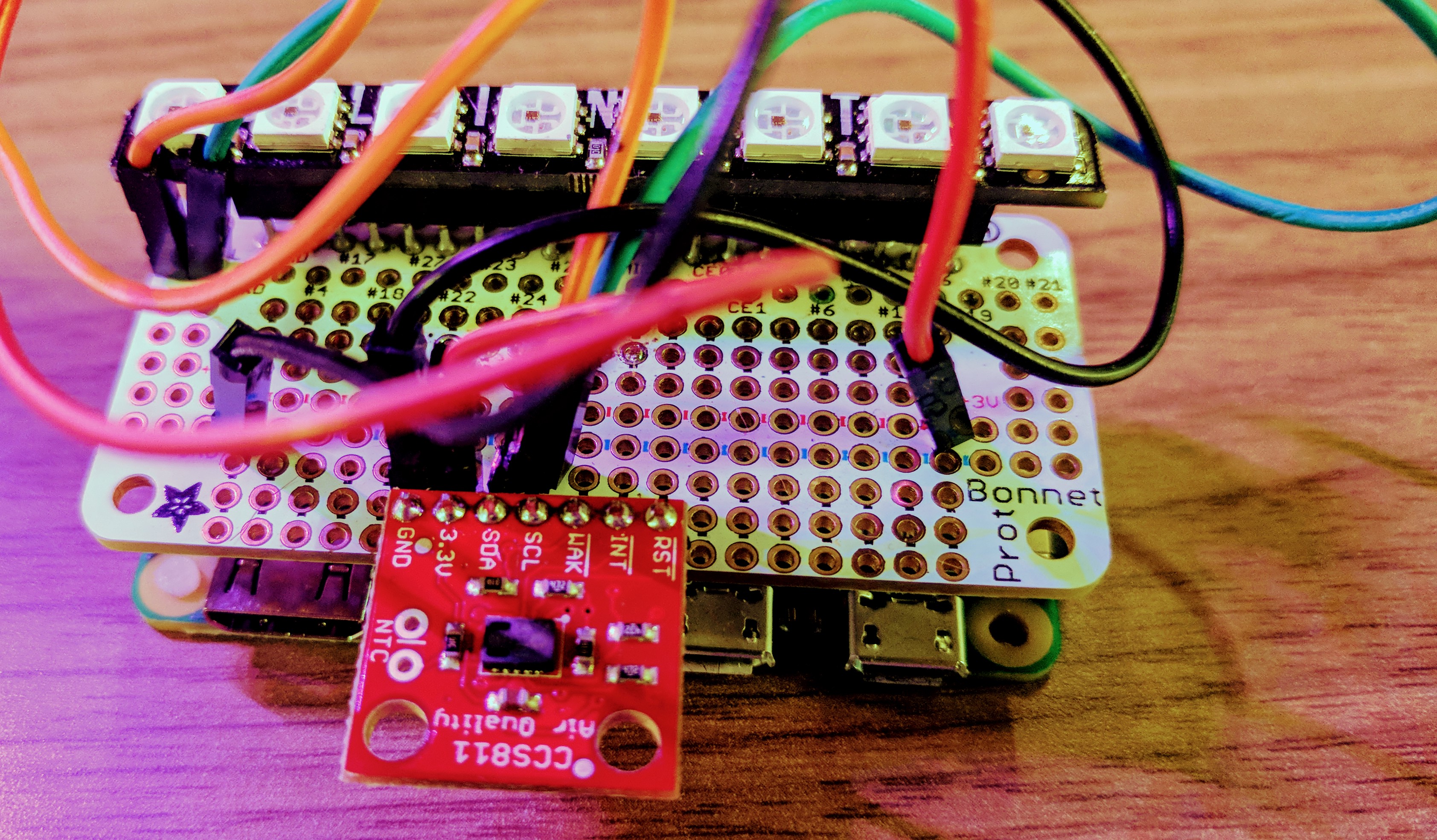
My intention behind designing a PCB was to avoid all the messy wires you would need while a prototyping board (or a “dot board”).
Same circuit (as above) but soldered onto a prototyping board
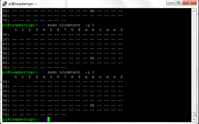
The PCB design was a simple one and I did not anticipate problems with the design. When I soldered the PCBs and began my testing, I was surprised to note that the sensor was not detected by the i2cdetect command.
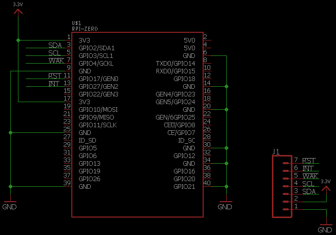
The circuit is very simple and the sensor breakout contains pull up resistors for the I²C interface. I had to draw four traces to interface the sensor (3.3V, GND, SDA & SCL).
The sensor breakout is equipped with a reset pin, a wake pin and an interrupt pin. All of them are active low signals.
Raspberry Pi Zero add-on board
In order to exploit the sensor’s features, I decided to interface those pins to the Raspberry Pi’s GPIO interface.
If you are an EE, you might me aware of the fact that GPIO pins are set to a high impedance state. I was aware of this fact but I also found out that while they are set to a high impedance state, they are also either pulled up or pulled down (Source).
The wake pin of the sensor breakout is connected to a GPIO pin (of the Raspberry Pi) that is pulled high in its high impedance state. I was wracking my brain to understand why the sensor wasn’t detected by the Raspberry Pi. My assumption was a bad solder or lack of continuity.
It turns out that a combination of current leakage (from the GPIO pin) and a weak pull-down resistor caused this headache. The sensor breakout’s reset pin comes with a 100K pull down resistor on the wake pin.
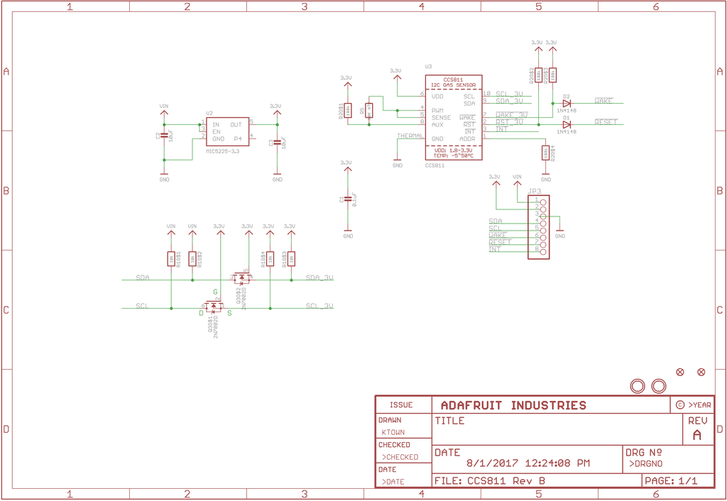
CCS811 schematic
It turns out that the 100K pull-down resistor was not sufficient to overcome the effects of leakage current. The wake pin was tied to “high” and put my sensor to sleep. I had to create a solder bridge between the wake pin and the ground pin. It worked like a charm!
I wonder if a stronger pull-down resistor would have solved the problem. I was conducting further investigation into the problem and I learned that pull-down resistors are a bad idea. Read all about it in Jack Ganssle’s article.
Adafruit has a similar sensor breakout and they used a pull-up resistor. You need to tie the pin to ground and it makes sense to me.
I think it is crucial to choose the right resistor value AND it is best to pull up your signal line (wherever possible).
I am never able to recall what I did in a particular year. But, I think 2017 has been an exciting year for me. Here are the things that come to my mind about 2017 (I collaborated with my brother on most of these projects):
I switched jobs and I moved from the West Coast to the East.
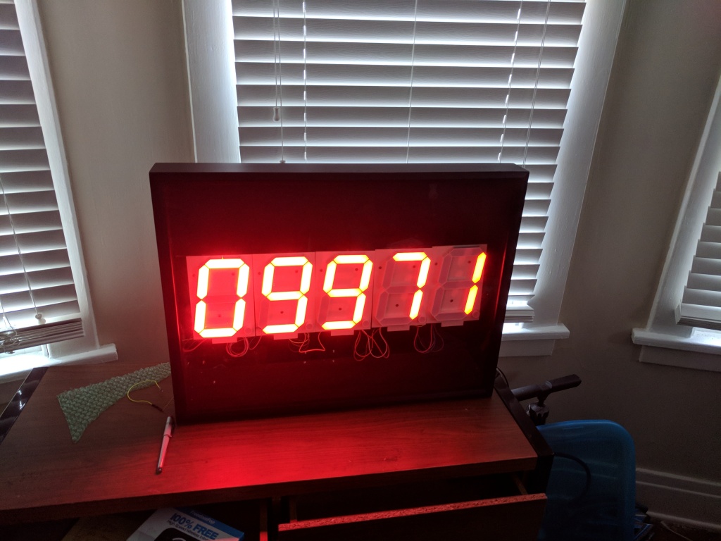
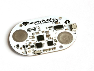
I am really proud of our exhibit at the Maker Faires: A Personal Health Dashboard
Personal Health Dashboard
Function of the dashboard
We built the personal health dashboard to motivate oneself to be physically active. It is driven by a Raspberry Pi Zero. We use a Fitbit tracker to keep track of our physical activity. Hence, we used the Fitbit API to build this dashboard.
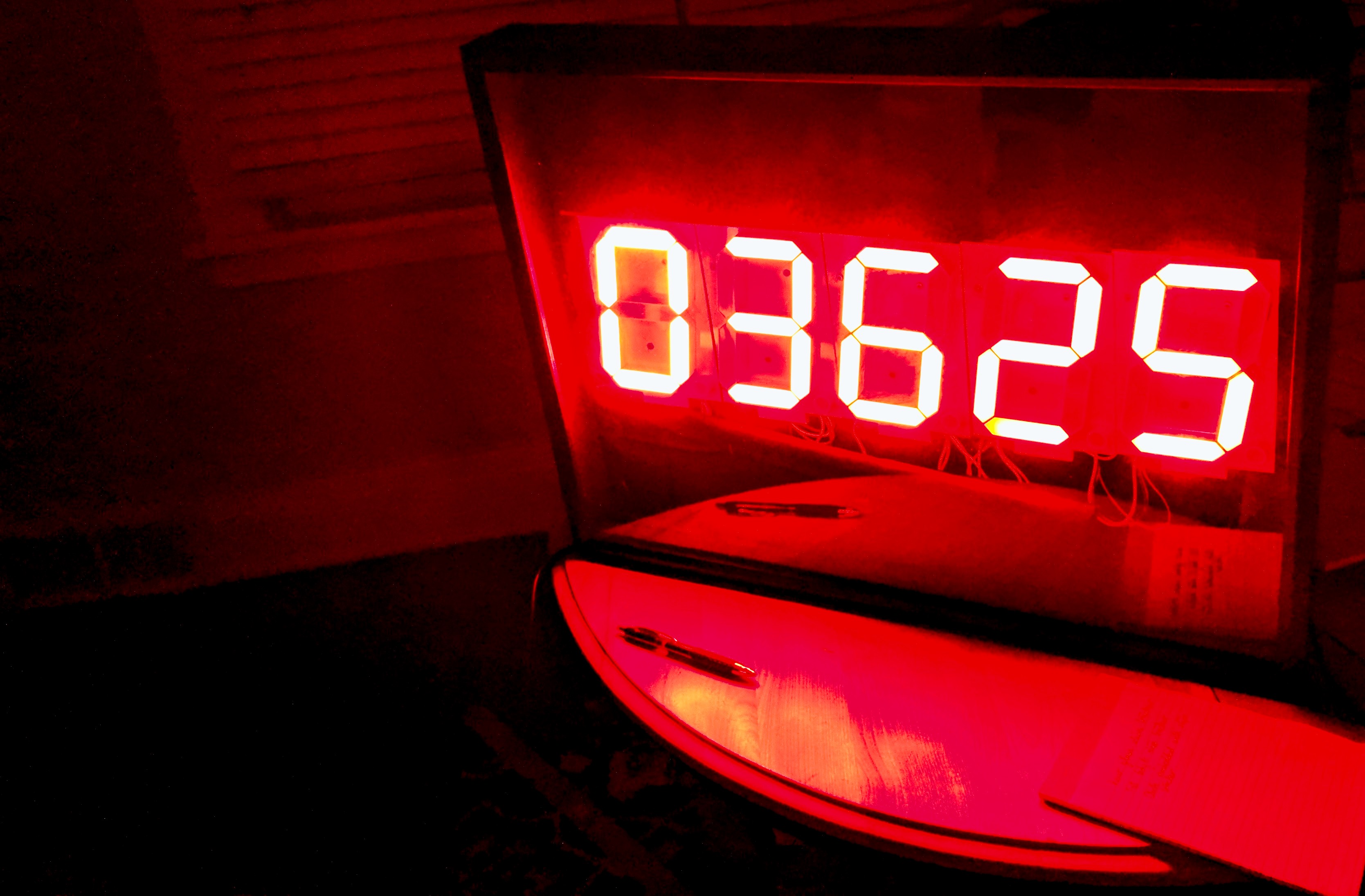
Every 15 minutes, the dashboard makes use of the Fitbit API to determine the total number of steps clocked for the day.
The dashboard counts down from the step goal using the steps clocked for the day. For example: In the above picture, I have about 3625 steps left for the day and my daily step goal is 11000.
We built two versions: one that counts up while the other that counts down. We found the latter to be useful since it informs you of the activity left for the day. You could plan your exercise accordingly.
Dashboard V1: Counts up to the step goal
Dashboard V2: Counts down from the step goal
We participated in 4 Maker Faires across the country:
World Maker Faire – September 2017 in Queens, NY
East Bay Mini Maker Faire – October 2017 in Oakland, CA
Cleveland Mini Maker Faire – November 2017 in Cleveland, OH
Rochester Mini Maker Faire – November 2017 in Rochester, NY
What did we learn?
Traveling is awesome
Our first trip was to the World Maker Faire in NYC. I picked my brother up from Cleveland and drove to New York City. It was an amazing experience.
I am someone who is always nervous before embarking on a trip. I don’t know why but this is slowly changing since I started traveling frequently. We also got to visit the Adirondacks region in Upstate New York:
Adirondacks, Upstate New York
Maker Faires are a source of entertainment
You get to meet a lot of people at the Maker Faire. It is important to visit other booths at the Maker Faire. They serve as a source of inspiration for future projects. We got to meet Lady Ada from adafruit.com, John Park from Adafruit, 3D Printing Nerd, the dude from Maker’s Muse. I strongly recommend visiting other booths at the Maker Faire:
We also witnessed some major announcements in the Hardware World:
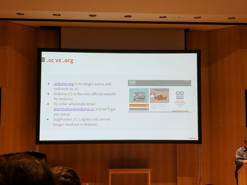
The Arduino Foundation announced some major changes to their organization: Arduino.org and Arduino.cc merged to become a single entity
Massimo Banzi’s announcement at the World Maker Faire
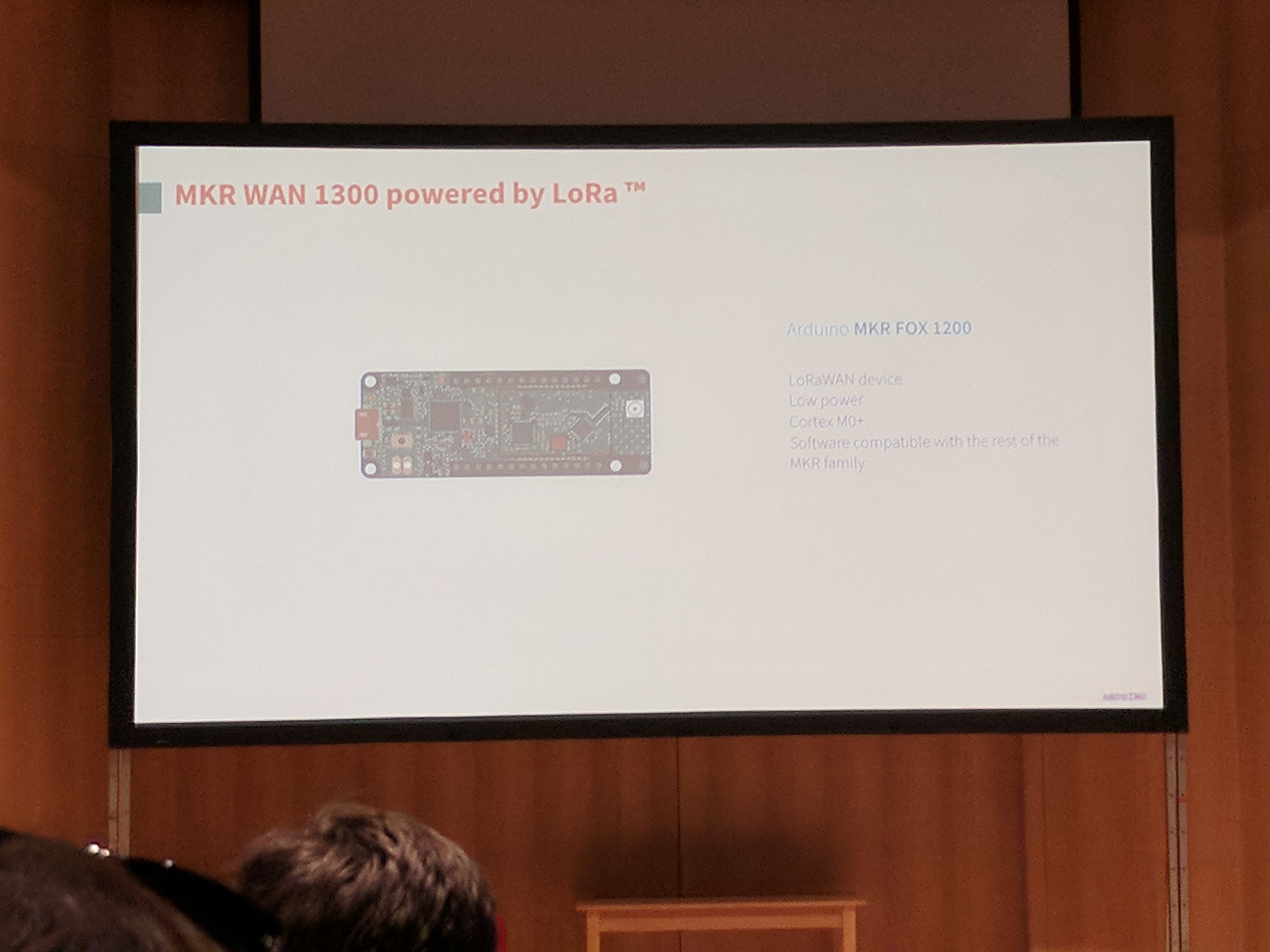
They also announced some exciting new hardware:
Massimo Banzi’s Hardware Announcement
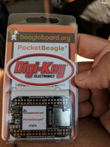
Freebies:
We got a lot of freebies at the Maker Faires. Our favorites include:
If you haven’t used the Eagle PCB design tool lately, you will be surprised to learn that it has underwent a major update since it was acquired by Autodesk.
Eagle’s license model has been switched over to a subscription service and I am liking the experience so far. I am able to get the latest updates of the software (unlike earlier, the updates are quite frequent). I am currently using Eagle 8.5.x and it comes with the “Push and Shove” feature that automatically pushes signal traces while routing your PCB.
PCB Outlines
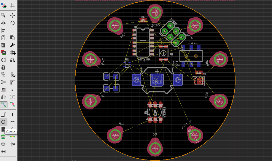
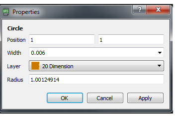
I was working on a circular PCB for building something like a fidget spinner. I assumed that I could draw circular PCB outlines by drawing a simple circle.
Circle feature in Eagle PCB
Being able to draw circular outlines can make your life easy. For example: You could draw a random circle and specify its radius, center etc (similar to Mechanical CAD tools).
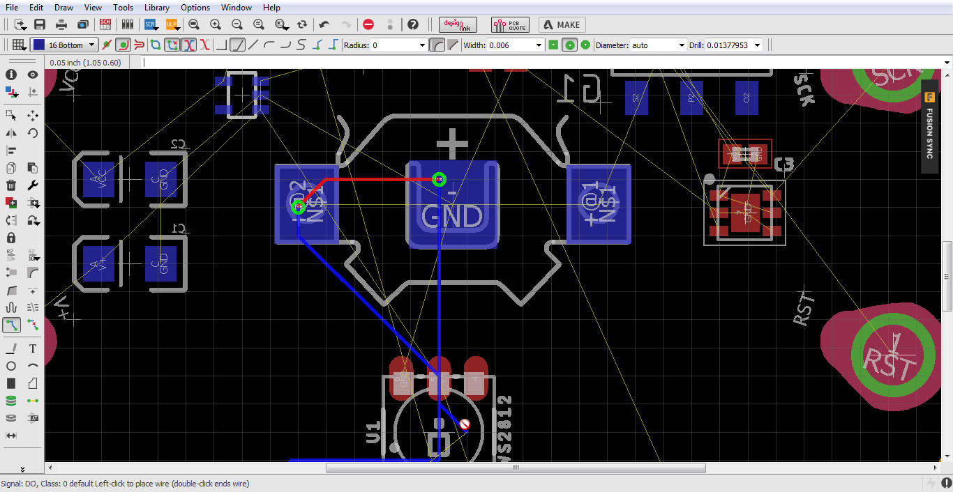
It turns out that the software considers this an error. When I started to route the PCB, the automated DRC check ignored glaringly obvious errors.
Errors resulting from the Circular Outline
In the above snapshot, you will note that I am able to route traces over PCB pads and the cursor indicates bad news.
After wasting some time, I found out from this forum thread that I need to draw my outline using arcs.
In Eagle, drawing an arc is a three step process:
Specify the starting point
Move the cursor to specify the arc radius
Draw the arc
It is definitely confusing and imagine drawing a “closed circle” using arcs. It can be frustrating.
I eventually managed to find a simple solution that involves combining arcs to draw circular outlines. Check it out!
I am no video expert. I made this video using basic screen capture tools. I look forward to hearing your tips on improving the video.
I really hope Autodesk simplifies creation of non-standard outlines. Did you have a similar experience? Drop your thoughts in the comments section!
My design is off to OSH Park. What manufacturing house do you use for your designs? I will share my build in upcoming blog posts.
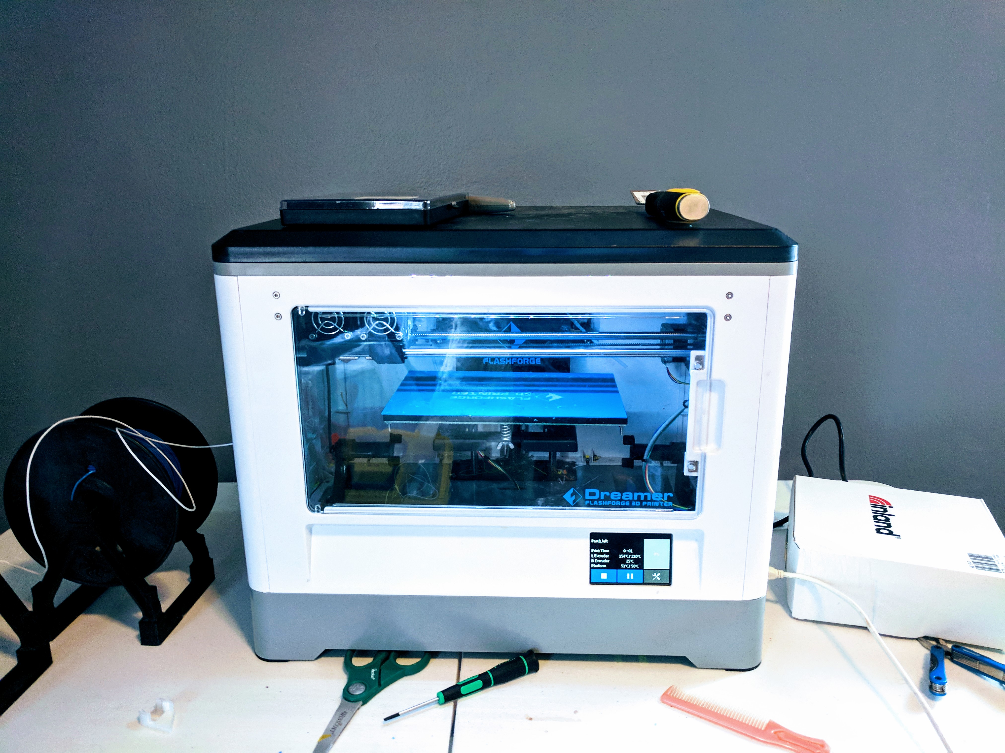
I finally got around setting up my 3D printer over the Labor Day weekend. I needed the printer for my World Maker Faire preparations (Psst.. Stop by our booth if you are in the area).
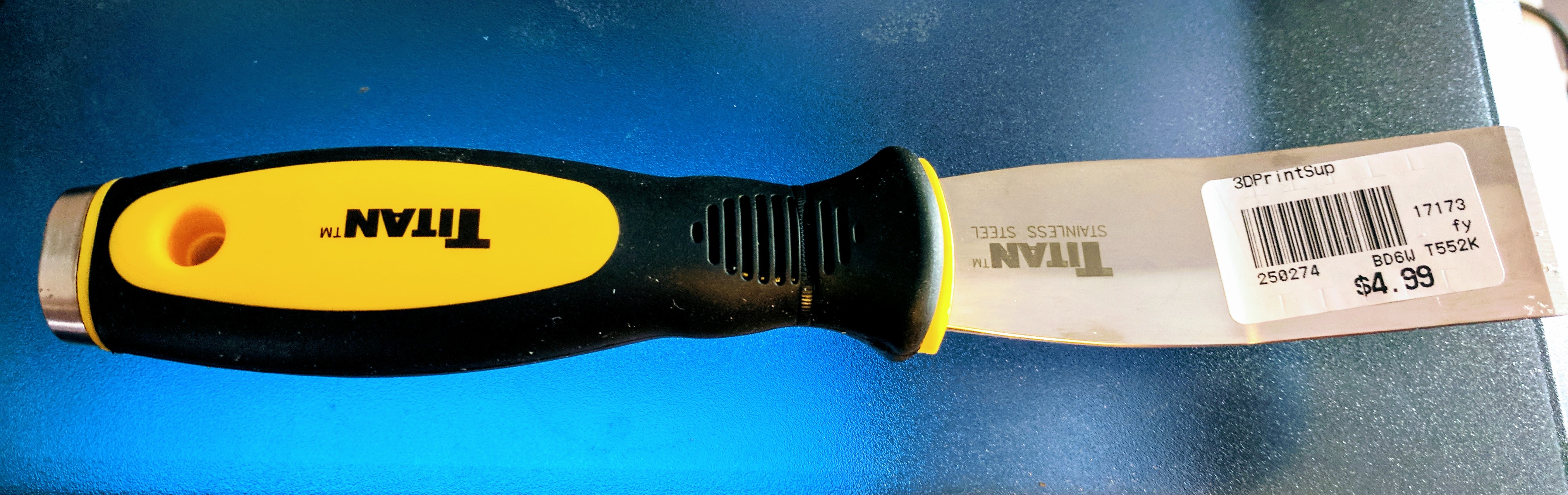
Since my move to Buffalo, I haven’t unpacked all of my boxes and I cannot locate some accessories like 3D print removal tool, Kapton tape etc. I tried removing the first print using a pair of scissors and cut my fingers.
I decided to get a 3D print removal tool and I could find only one store in Buffalo that sold 3D printer accessories. You can visit the store only by appointment.
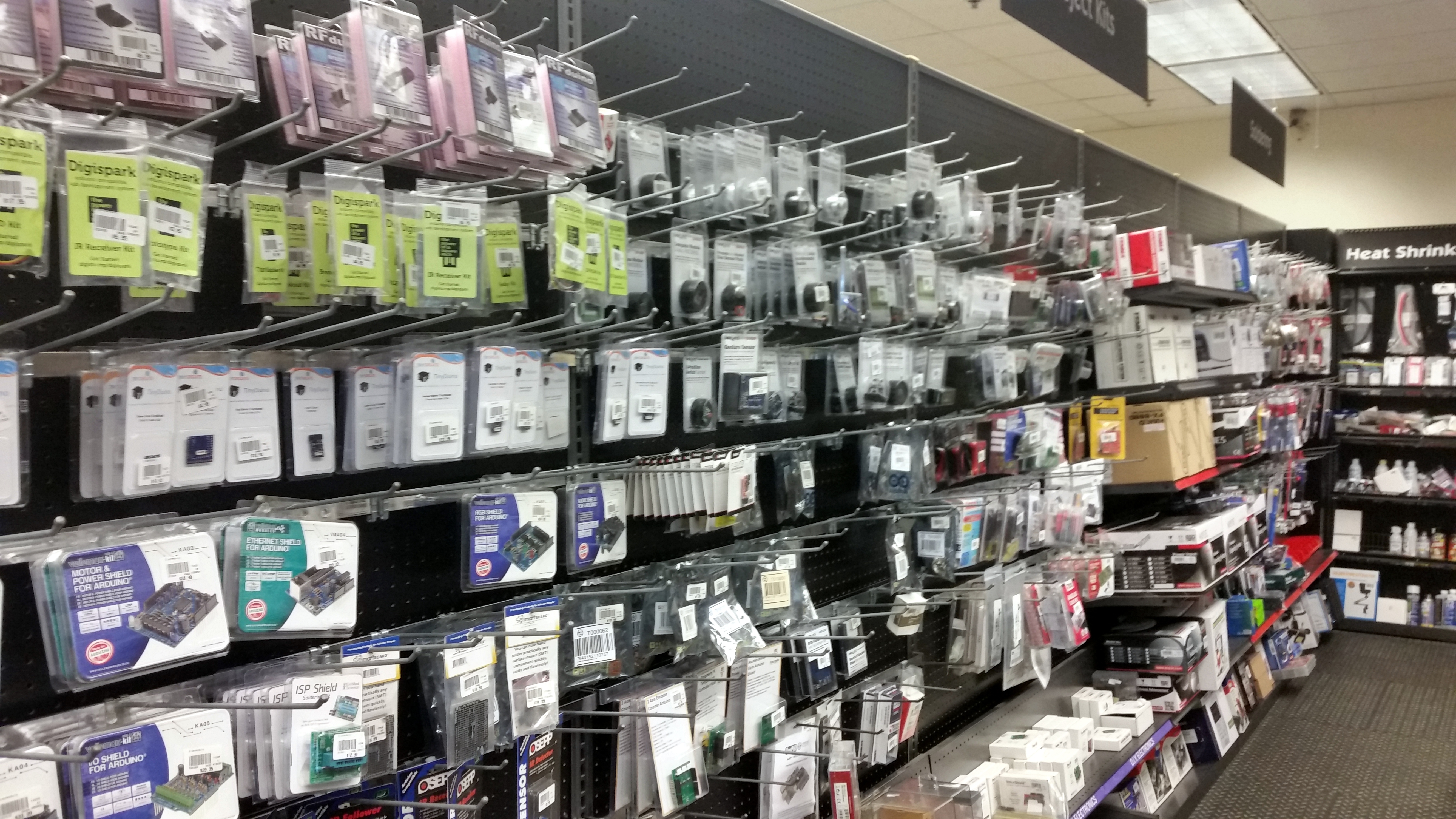
The alternatives were Micro Center in Cleveland or Amazon. I chose the former and drove to Cleveland (I am a bit crazy). Micro center is an official distributor of the Raspberry Pi and they carry everything from Arduinos to 3D printers, filaments and other accessories.
Microcenter’s DIY stash
I got a spool of color changing filament, 3D print remover and a Raspberry Pi Zero W.
I think the options are limited when it comes to in-store purchases related to 3D printing in the Rust Belt. Fry’s electronics has stores in Chicago and Podunk, Indiana. Micro Center has stores sprinkled across Ohio.
It appears that Micro Center’s employees rely heavily on sales commission. Employees chase you around to help and stick a label on your selection. They keep hovering over you and I was not comfortable taking a picture of their 3D printing aisle.
I miss the SF Bay Area as I could have solved my problem by crawling through Craigslist or going to Fry’s Electronics (The Bay Area has about 3 or 4 Fry’s branches).
After a 6 hour trip, I got to put the remover to good use.
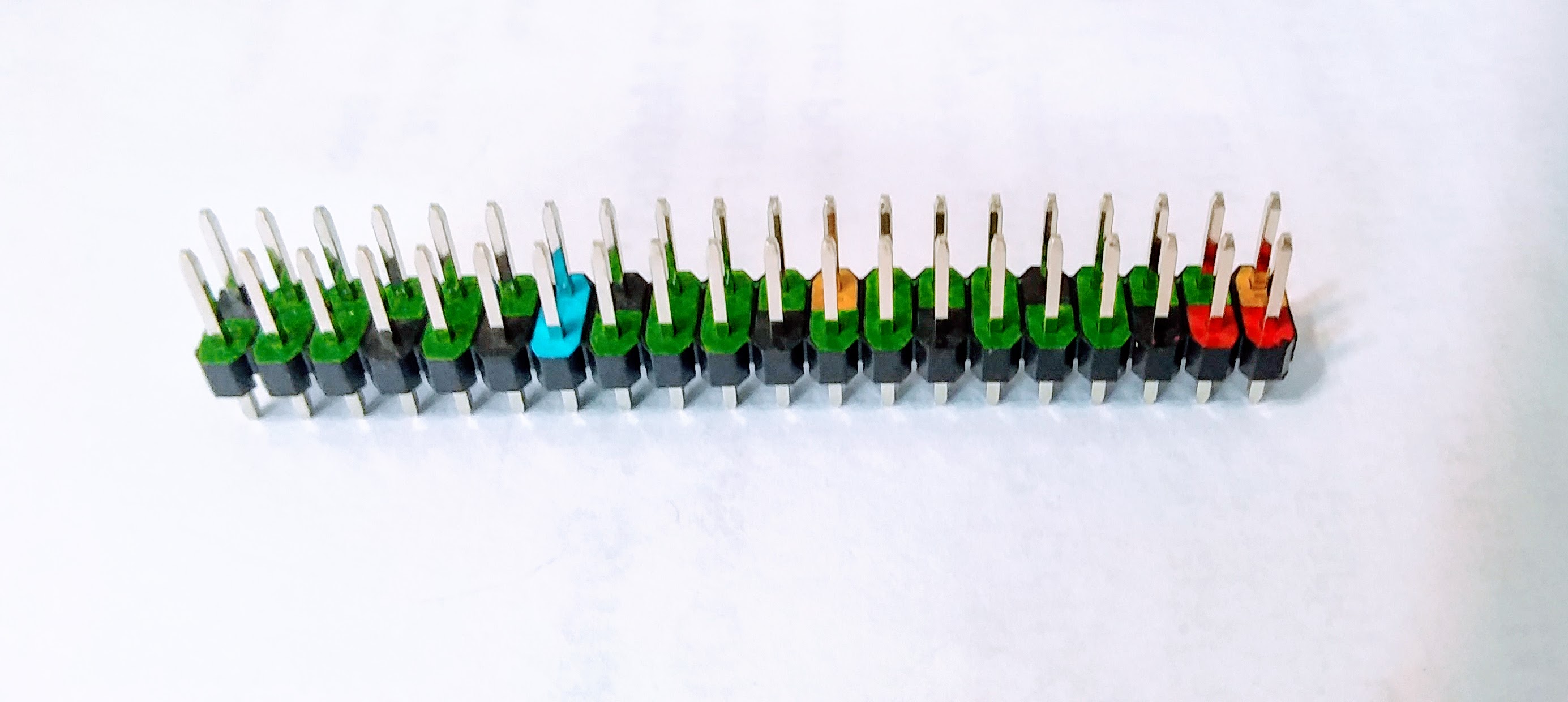
I came across this color coded GPIO header for the Raspberry Pi Zero from the Pi Hut. This can be really useful while prototyping a circuit. 5V pins are coded red, 3.3V pins are coded yellow, Ground pins are coded black.
It can help avoid connections to the wrong pin.
I usually refer to the GPIO pinout when I am connecting to the UART or the I2C interface. I always mix up the pin names. I wish the header had side labels like the Arduino.
Given the header height, I guess it is not practical to have labels. You can buy the headers from here.
This week is being celebrated as the National Week of Making by Nation of Makers – a nonprofit dedicated towards supporting the maker movement in the United States.
When the new administration took charge of the White House in January 2017, they took down all pages related to the maker movement in the United States. It is not known whether these pages would be restored in the near future. I learned this from watching Adafruit’s Show and Tell and I also learned that Nation of Makers decided to take lead on driving the maker movement.
They are encouraging makerspaces to conduct maker townhall events by offering grants to them. I promised myself to celebrate this week by building something useful (another blog post coming soon!).
I also wanted to share some interesting news to celebrate this week. Digi-Key and Adafruit announced that they will be donating a Circuit Playground to Girls Who Code for every Circuit Playground sold on their website. Check it out!
I also recommend checking out this week’s Ask an Engineer episode from Adafruit (shared below). Happy Making!
We came across a tool called Etcher from Resin.io. It is a tool meant to flash an image onto an SD card. This is especially useful to quickly setup your new Raspberry Pi. It is a one step process where you can select the image and flash the SD card for your project.
We put together a video that shows how to flash an image for your Raspberry Pi:
I wanted to document my projects in vivid detail. Recently, I 3D-printed an enclosure for the Raspberry Pi Zero W. I recorded the printing process. The enclosure consists of two halves. The top piece broke while trying to remove it off the bed. In my second attempt, I printed the top piece separately and managed to remove it carefully.
Psst: I am learning to make good videos and I look forward to hearing your feedback
It appears that this following development kit is necessary to follow along with the webinar. I will share my experience after watching all the webinars. The webinars are recorded for posterity.
I usually back Kickstarter projects(in the DIY electronics domain) that peek my interest. I recently backed the Pine A64, UP and the Latte Panda boards but the Jaguarboard is not one of them.
I usually look for a cool feature that would enable me to build a cool project using the backer reward. For e.g. The Latte Panda comes with onboard Wi-Fi/Bluetooth. It has an ATmega32U4 microcontroller that enables easier interface of sensors.
The Jaguarboard failed to impress me for a couple of reasons:
Lack of sufficient GPIO count – They provide access to only 4 GPIO pins. I usually make use of more than 4 GPIO pins in my projects. However, it does come with an I²C port which could be used to expand the GPIO capabilities.
Incompatible with the Raspberry Pi/Arduino add-on boards – It is not possible to port Raspberry Pi/Arduino projects that makes use of an add-on board to the JaguarBoard platform. It also doesn’t make sense developing expansion modules for the JaguarBoard as the lack of a broad user base is a distinct possibility.
Comparison of specs on the campaign page – The campaign creators have compared the specifications of the board to the Raspberry Pi Model 1 rather than Model 2. The Raspberry Pi Model 2 comes with 1 GB RAM while Model 1 comes with 512 MB RAM. I think that is not a fair comparison.
Unrealistic campaign schedule – In my opinion, the promised delivery date of the board is a tad unrealistic. They promised to deliver the boards by January 2016. The Kickstarter campaign itself ends only on January 22, 2016. As far as I know, Kickstarter takes at least 10 days to transfer the campaign money to your pocket. This puts the campaign roughly in the first week of February. Unless the campaign creators, plan to ship the boards using money out of their pocket, this is not possible.
They also have not released any planned timeline of the project. This is possible only if they already have a stash of boards manufactured, packed and stored in a warehouse.
In summary, I am not impressed by the JaguarBoard Kickstarter campaign.
The Adafruit Metro is a variant of the Arduino Uno. It is enabled by an Atmega328 microcontroller. The main distinction between the Metro and the Uno is the chipset used for the virtual COM port. While the UNO makes use of an Atmega16 family microcontroller for the USB interface, the Metro makes use of the FT231X chipset.
I liked the red color and ordered a unit for myself. The rear side of the PCB contains the Adafruit Metro’s BOM from DigiKey.
Adafruit Metro
Adafruit Metro Rear side
At the time of writing this post, the special edition Metro was still in stock @ DigiKey. The packaging gave me the impression that the board could have been possibly manufactured by Adafruit on behalf of DigiKey.
I have been frantically printing ornaments for the Christmas tree using my new M3D printer (my review of the M3D coming soon). The incessant printing clogged my printer yesterday and I needed a steel wire to unclog the extruder.
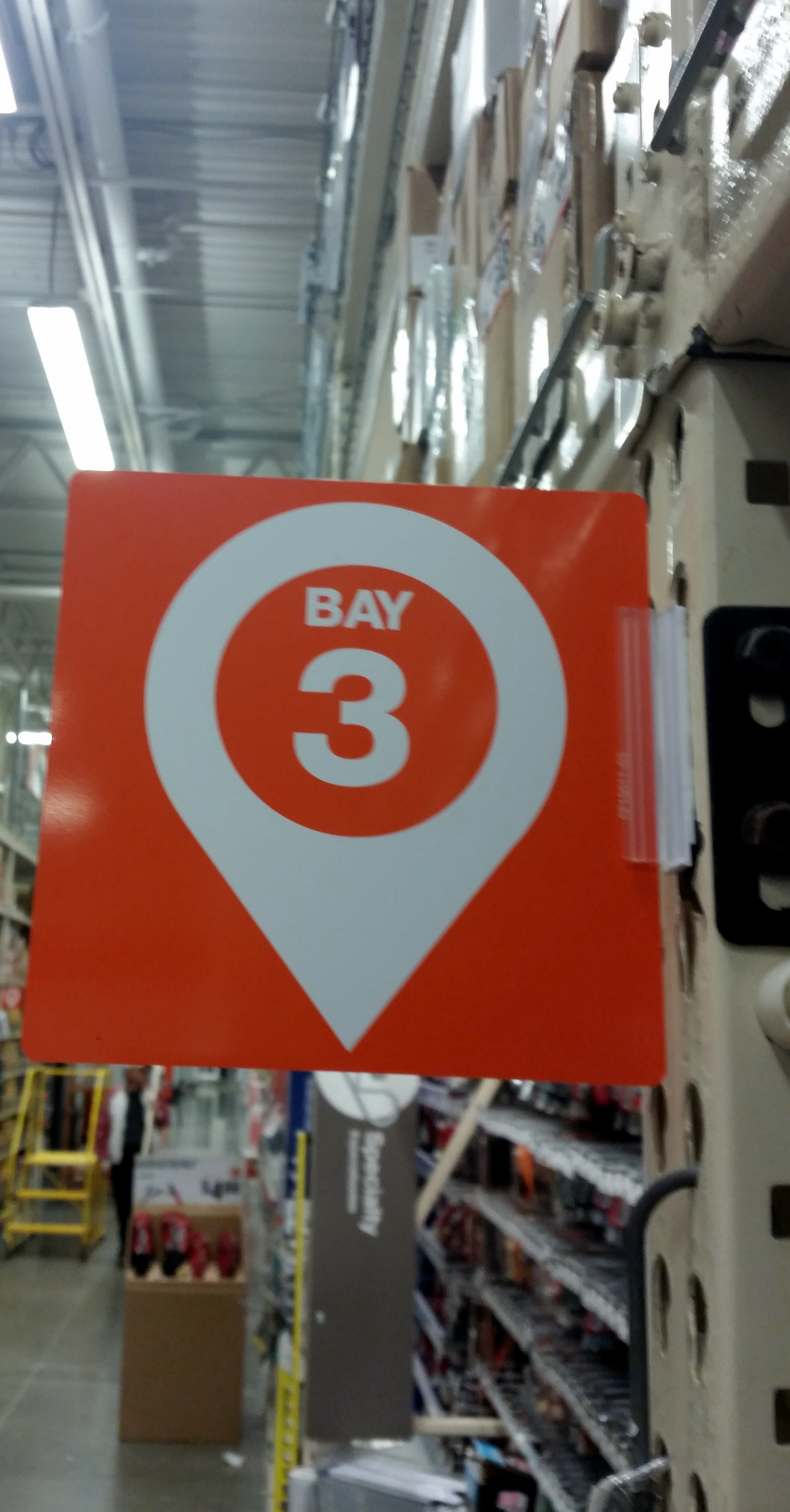
I checked the availability of a steel wire at the nearest Home Depot using their website. Apart from providing the availability information at a particular store, Home Depot also provides information related to the aisle where the steel wire is located. I was surprised to find additional information including the ‘bay’ where I could find this steel wire. The site also has provisions to text this info to someone.
Location of the item inside the store
I was not sure about locating the item at that particular aisle using the bay information. It turns out Home Depot has started labeling different sections/bays of an aisle using numbers.
Bay Numbers at Home Depot
Home Depot is probably maintaining its inventory at all stores using RFID readers, bar code scanners etc for a while now.
I am glad that they have started helping their customers by providing more resolution to the location of an item in a store than merely stating that “Item X is available at your local store”.
At this year’s ARM TechCon keynote sessions, one of the speakers noted that we are past the era of designing variations of connected sensors. He pointed out that companies have started directing their focus towards enforcing behavior change using connected devices.
It is interesting to learn that stores like Home Depot have already started helping their customers save time by sharing more information about their products using their existing infrastructure of connected sensors.
I am certain that Home Depot has invested in some user experience research to improve their web store shopping experience (for e.g. Paypal integration, text messaging option on the item’s web page) as well as enhance the shopping experience using their current infrastructure of inventory scanners.
Yep, you read that right! I had to drive 392 miles to get a $5 Raspberry Pi Zero! I plan to share the details of my trip in a later post. While I did this trip for fun, it is quite difficult to buy some discrete components in the Bay Area.
Chicago v.s. S.F. Bay Area
Chicago
I lived in the Chicago suburbs for 2 years and 3 months before I moved to the Bay Area in May/June 2014. While living in Chicago, I had several options to buy discrete electronic components:
Microcenter– (2 stores in Chicago!) – Carries a lot of DIY kits (I am not talking about the Arduino and Raspberry Pi). Open Sundays.
American Science and Surplus (Milwaukee/Foster Ave neighborhood) – This store sells stepper motors, cool DIY science kits, test tubes, conical flasks etc. Open Sundays.
Chicago Electronics Distributors (Winnetka)- A distributor of Adafruit products. This guy is awesome. He used to let me arrange a late evening local pickup for emergencies. I do not recall buying anything on a Sunday from this guy.
Radio Shack – This is no longer an option but Radio Shack carries a couple of components.
Given these options, I could always find a part locally (unless my requirement is very specific/exotic).
Hackerspaces:
There are 3 hackerspaces in the Chicago area. Pumping Station 1, Workshop 88 and the South Side hackerspace. I was a member of Pumping Station 1. It was so easy to build your own enclosures using a laser cutter. Pumping Station 1 is easily accessible from different parts of the city and the starving hacker membership was approximately $40 a month.
S.F. Bay Area:
Radio Shack – This is no longer an option. Radio Shack has gotten rid of a part its DIY electronics shelf. Now you could buy some basic accessories like solder.
Fry’s electronics – Open Sundays. You could buy some discrete resistors, capacitors etc. Arduino kits etc are ridiculously expensive.
Jameco – They have a store front in Belmont. They are open only Mondays to Fridays, 9 a.m. to 5 p.m.. It is best to order your stuff online and pick it up. They sell a variety of discrete components, kits etc. They do have an online chat support to discuss your order. Good luck driving from San Francisco to Belmont in rush hour traffic.
oddWires – This store also allows local pick up but only on week days. I have never used this store as it is very far away from where I live.
Hobby engineering – This store provides pickup on all days of the week upon prior arrangement. Their store collection is not so extensive and I never had the chance to use their business.
Evil Mad Scientist (Sunnyvale CA) – A re-seller of Adafruit products and they also carry a lot of DIY electronics kits. The pickup option is available only on week days during business hours.
Al Lasher’s Electronics – This store is open 8:30 a.m. to 5:00 p.m. on all week days and 8:30 a.m. to 2 p.m. on Saturdays. They are a distributor of Sparkfun and they do sell a vast variety of components that peeked my interest.
A sign inside Al Lasher’s electronics
Al Lasher’s electronics, Berkeley CA
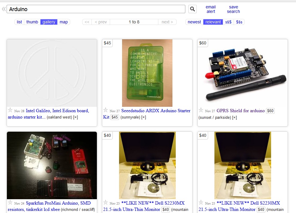
Craigslist!!!
If you have plenty of time in your hands and if you are trying to buy an Arduino or a Raspberry Pi, you can try crawling through craigslist. If you are lucky, there might be some one in your area who is trying to getting rid of their electronics stash.
Search results for arduino in the SF Bay Area Craigslist
Update (06/21/2017): A reader left a note in the comments about HSC (Halted Electronics) and Anchor Electronics in San Jose. I have been to Halted Electronics in San Jose. It is a big store and they carry an array of components but you have to be patient going through different aisles. If you are looking for cheap DC motors, HSC is a great resource. I haven’t been to Anchor Electronics. Thanks Travis!
Hackerspaces
I learned of 2 hackerspaces in the Bay Area namely Noisebridge and Tech Shop that is equipped with tools like a laser cutter. While TechShop is a bit pricey, applying for Noisebridge’s membership is a tad complicated. You need two members who could potentially support your membership application. This is probably to prevent abuse of the hackerspace equipment. Given my socialization skills, securing a membership is next to impossible. I decided to navigate this situation by getting my own 3D printer.
It might appear that the Bay Area has several options for a hobbyist. It is just difficult getting to these places when they are open.
As you may have noticed, most of these places are open only on week days except for the hackerspaces. The traffic in the Bay Area is insane until around 7 p.m. (more like 7:30 ish). Most of these stores are closed for business by 7 p.m..
When I was at the Orange County Microcenter to buy the Raspberry Pi Zero, I recalled all the options I had back in Chicago. I was told that there used to be a Micro Center in the Bay Area but they had to shut down.
Fully stocked aisles at the Micro Center
The Bay Area is home to a lot of semiconductor manufacturers, smart device manufacturers etc. Yet, you have to go online to buy parts for your project.
As the title states, the S.F. Bay Area is not a haven for the electronics hobbyist.
P.S.: If you know of a great resource that I missed here, leave a comment.
The Raspberry Pi foundation announced a new variant of the Raspberry Pi this morning (around 2 a.m. ET). It is called the Raspberry Pi Zero. I have written more about it in this post. Check it out!
The Pi Supply store is giving away a Raspberry Pi Zero to a lucky winner. Entries are accepted until December 2, 2015 and the winner would be announced on December 6, 2015. Click this link to enter the contest.
Disclosure: For every person that enters the contest using the above link, the chances of my winning increases since I get 3 entries for every referral. Do enter the contest if you are interested.
Comments Off on Raspberry Pi Zero + Pi Supply’s giveaway | Uncategorized | Permalink Posted by yamanoorsai
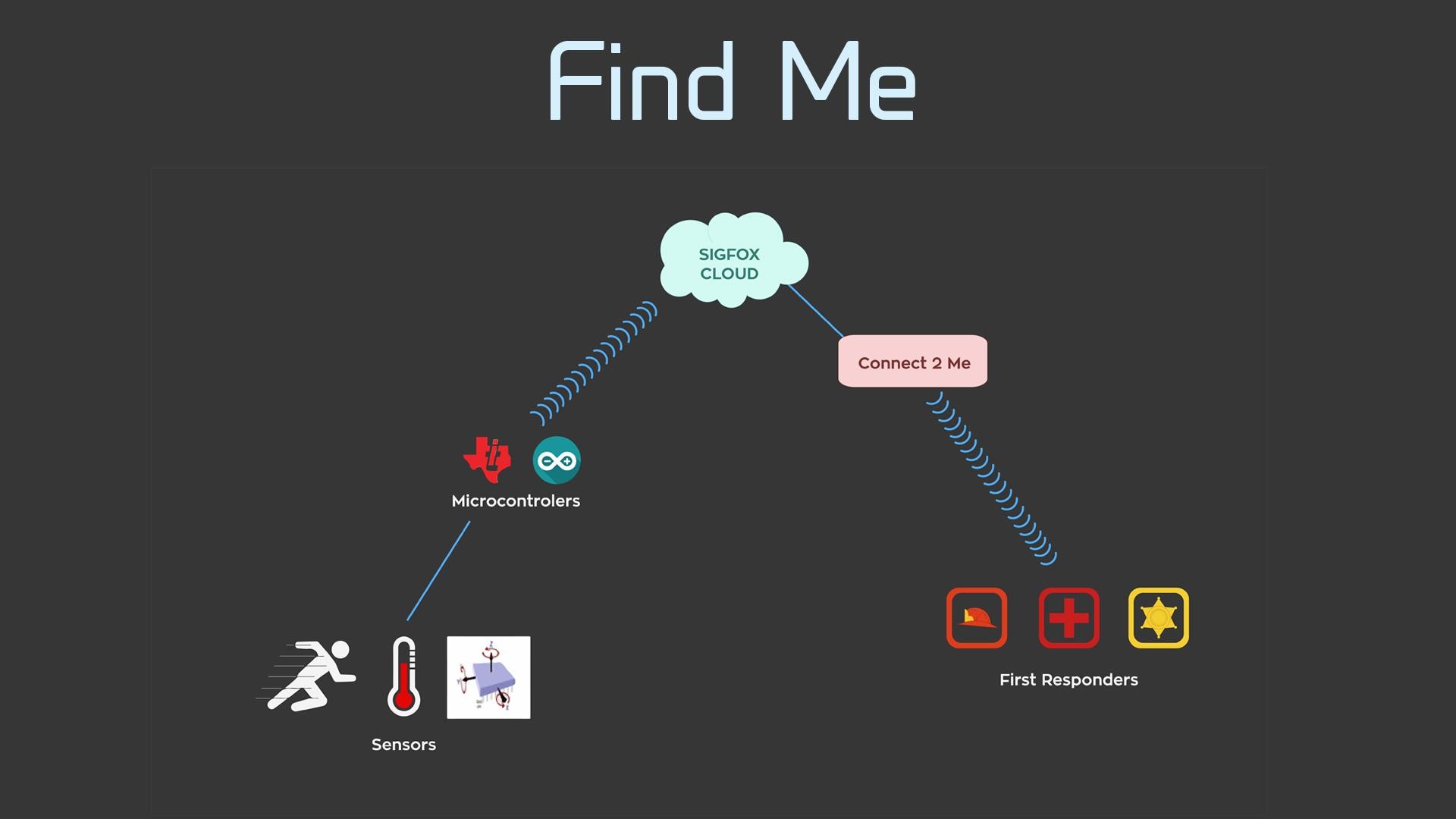
Sigfox is a European company that has installed low power wide area networks across several cities in Europe and San Francisco. Sigfox’s radio network enables interfacing low power sensors to a network enabled by radio transceivers installed in San Francisco’s public libraries.
This radio network enables transmitting a 12 byte message at a time and it is capped at 140 messages per day. This network is very useful in the case of interfacing sensors that do not provide real time updated. For example. sensors that report their status every hour or so, panic buttons that transmit emergency alerts to first responders etc.
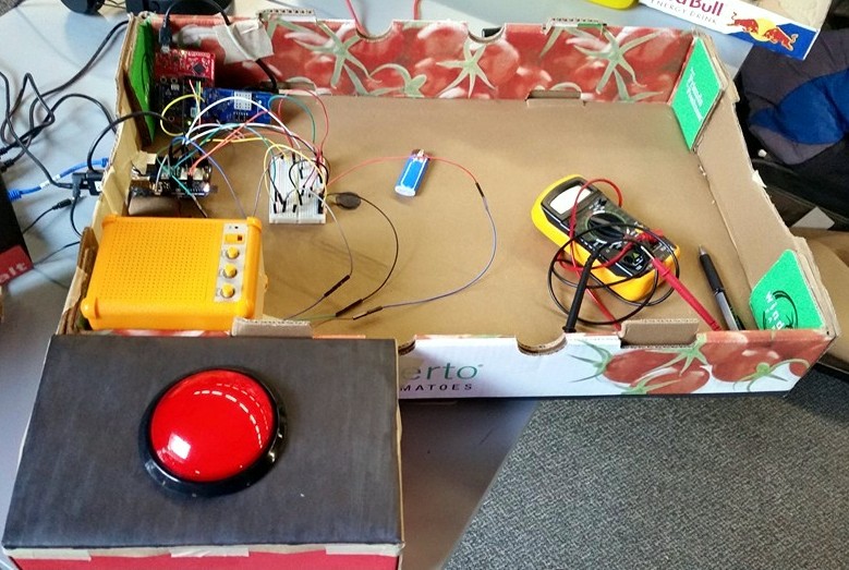
My team picked a project that enabled collecting information related to the number of people assembled in any room of a building. This information is transmitted to the Sigfox network in the event of an earthquake (detected by an accelerometer installed in the building) or whenever a panic button is pressed.
We also used a PIR sensor, temperature sensor and a force detecting sensor to simulate events like large pillar columns falling down, buildings catching fire etc. This information could be used by first responders to effectively deploy resources in an emergency.
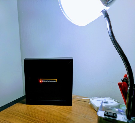
We built two gadgets. I built one of them and is shown in the figure below. It includes a panic button, temperature sensor and a force detecting sensor.
Gadget that I built includes panic button, temperature and force sensors
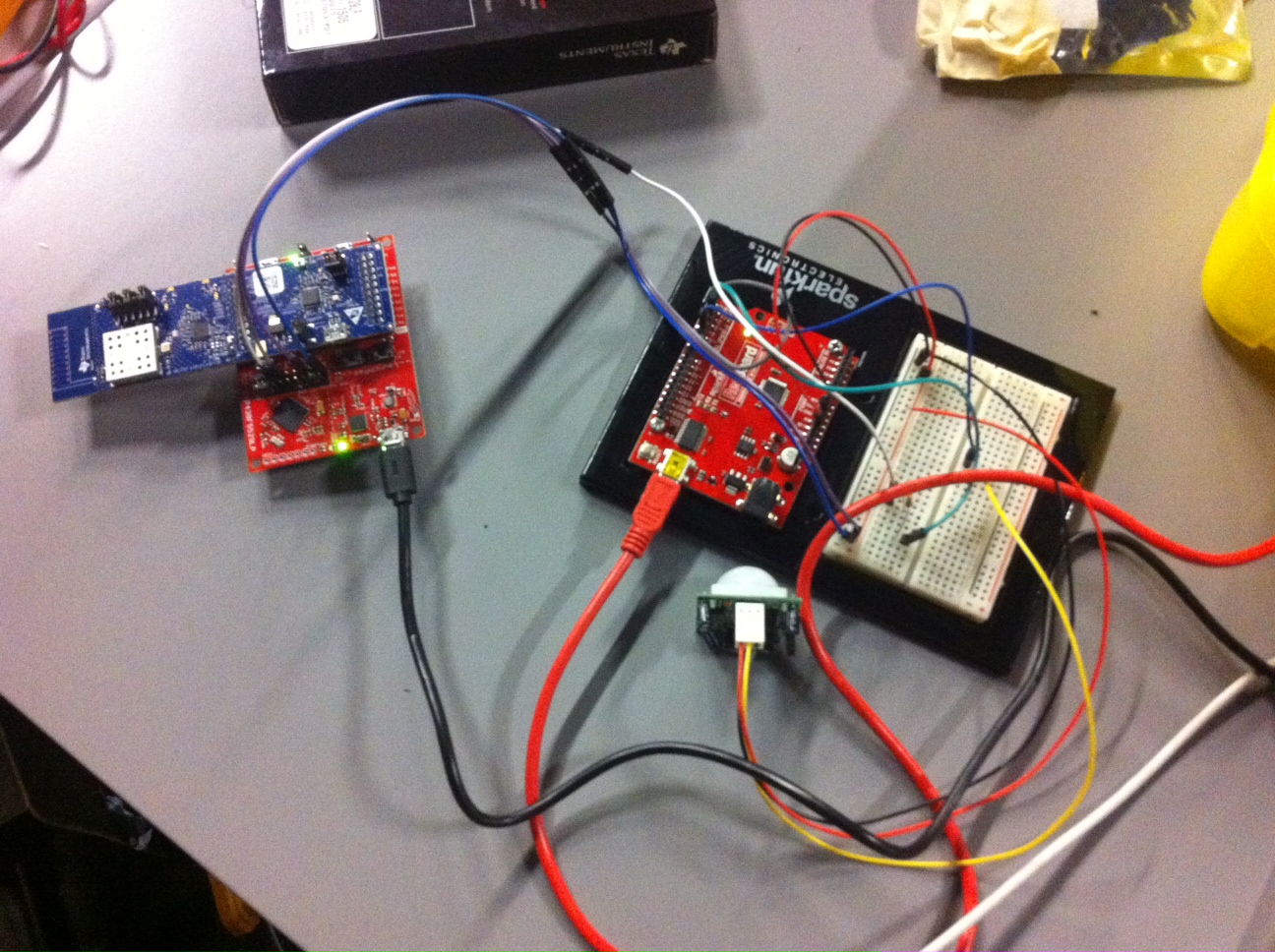
My team mate Yingxian built another radio that gathered information from an accelerometer and a PIR sensor.
Photo Courtesy: Yingxian Wang
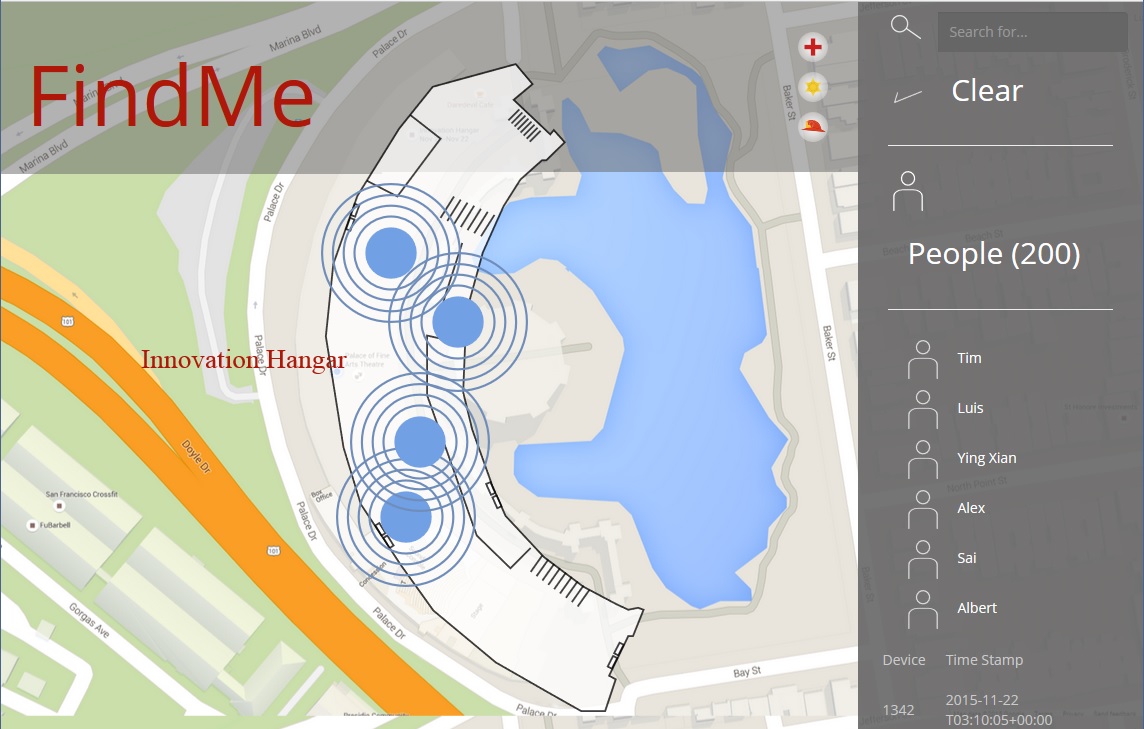
The radios transmitted the messages to the Sigfox radio network. The transmitted messages were supposed to be used for visualization in a web dashboard like the one shown below.
Dashboard by Tim Strickland
How does this gadget work?
The figure below provides a simple description of how these radios interact with the “cloud”.
We got an unlimited evaluation license for our radios and our radios did not have any daily cap on the number of messages that could be transmitted to the network for development purposes.
The radios were very easy to use. They transmit any message received through the serial port. We used an Arduino Yun to interface our sensors. The Arduino Yun transmits the message to the radio via serial port. It also talks to a processor running linux on the Arduino Yun. Here is a short video of my project: It sends an emergency alert to the Sigfox network and plays an audio alert.
Here is another video where we simulated an earthquake. My teammate, Yingxian wrote the code to detect earthquake like movements to detect earthquake simulations using an accelerometer.
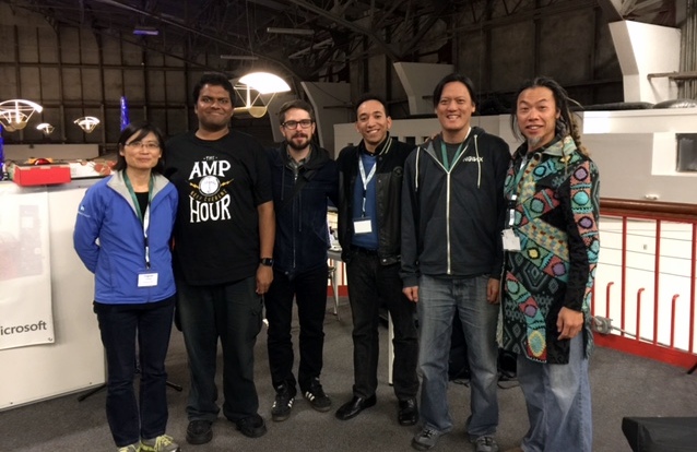
My team
I met my team mates at the hackathon and I am amazed by how we were able to get along with each other. Here is a pic of my team after the hackathon prizes were announced.
Left to Right: Yingxian, me, Tim, Louis, Albert and Alex.
Who were the winners?
AudioArgus – A team that built a service that predicts faulty rotary/reciprocating equipment requiring service and alerts the city about it. I see this as a project that enforces behavior change using the Internet of Things.
Dry Water – A water sprinkler controller project that considers several weather factors to turn on/off a sprinkler. I see this one also a behavior change tool by building connected devices
There was also a bike project that enabled enhancement of bike rental experience. I am not sure that I am able to recall the project’s theme correctly.
The radio network’s coverage spans between parts of San Bruno in the San Francisco Bay peninsula, Hayward in the eastern side of the Bay, parts of Marin County and Berkeley.
The sketch used to transmit messages is available from here.
What next?
I had fun working on this project last weekend. This has motivated me to register for another smart city hackathon on December 5th. If you are interested in working on a similar project (not the same one) at that hackathon, you should write to me @ yamanoorsaiatgmaildotcom or ping me via twitter using the same handle.
I was trying to determine if it is possible to remotely flash firmware on an ATmega2560 microcontroller using a micro SD card. I came across this repository of an ATmega2560 bootloader that flashes the microcontroller’s flash memory when a particular address on the EEPROM (Address: 0x1FF) is set to the value ‘0xF0’.
When the microcontroller is reset, if the EEPROM value(at address ‘0x1FF’) is set to ‘0xF0’, the bootloader looks for a file ‘firmware.bin’ on the SD card and flashes the microcontroller with the new firmware.
Adafruit Music Maker shield mounted on the Arduino Mega2560
I had to make minor modifications to make use of this bootloader. I changed the Chip Select pin number of the micro SD Card (there are tutorials that explain how SD cards are interfaced to microcontrollers) in the macro definition to match that of the Adafruit Music Maker shield (the micro SD holder’s chip select pin is connected to Digital Pin 4 of the Arduino. This corresponds to pin 5, PORTG on the ATmega2560. Source: Arduino Mega 2560 schematic).
In the file asmfunc.S, I changed the CS pin to pin 5 on PORTG:
This file contains bidirectional Unicode text that may be interpreted or compiled differently than what appears below. To review, open the file in an editor that reveals hidden Unicode characters.
Learn more about bidirectional Unicode characters
I also had to change the pin number of the LED used to indicate the progress of flashing the microcontroller by the bootloader.
This file contains bidirectional Unicode text that may be interpreted or compiled differently than what appears below. To review, open the file in an editor that reveals hidden Unicode characters.
Learn more about bidirectional Unicode characters
After recompiling the bootloader’s source files, I flashed the new bootloader using AVR ISP MK II. I also had to make sure that the BOOTRST fuse was set in the ATmega2560’s fuse settings.
ATmega2560 fuse settings
I compiled an LED blinking sketch and converted it into a binary file by executing the following command:
This file contains bidirectional Unicode text that may be interpreted or compiled differently than what appears below. To review, open the file in an editor that reveals hidden Unicode characters.
Learn more about bidirectional Unicode characters
Note: The Arduino IDE compiles and stores its hex files in a temporary directory. In order to save the hex file upon compilation, edit the IDE preferences after closing the IDE. The preferences text file can be located at File–>Preferences
Arduino IDE preferences
A line build.path has to be added to the preferences file. I included the path where the output of the compiled Arduino sketch would be located. I used Atmel Studio to convert the Arduino sketch’s hex file to a binary file (the avr-objcopy command shown in the above code snippet). I copied the binary file onto a micro SD card and inserted into the music maker shield’s micro SD card holder.
I made use of this sketch to set the value ‘0xF0’ at the address ‘0x1FF’. Upon reset, the bootloader flashed the microcontroller with the binary file located on the SD card.
Things to investigate:
1) When I was looking for a bootloader that would flash a microcontroller from an SD card, I read about problems encountered by others. I found out that people had problems using certain types of micro SD cards. I did have a hard time getting the bootloader working but it was due to the fact that I did not set the BOOTRST fuse.
Do let me know if you have used this bootloader or something similar in the past.
Reblogging my own post from another site: I am traveling this memorial day weekend and I wrote a post on setting up your Raspberry Pi in a motel room to verify something quickly for a presentation etc.
I own a couple of multimeters and I am never able to find one when I need them. I relocate my residence constantly and hence end up leaving the multimeter in one of the random boxes and forget where I put it (next time, I plan to mark my boxes clearly) and I never unpack my boxes due to my laziness.
My brother shared this USD 8 multimeter deal on Newegg. I decided to get one as I find Radioshack multimeters to ridiculously overpriced. I consider the deal to be a steal and comes with a backlight (apologies for the low quality picture). The multimeter is available on sale from here.
Silicon Labs has announced an Internet of Things (IoT) contest recently. The contest revolves around building an application around the SIlicon Labs microcontroller. The winning project gets USD10K worth of components for building your own product
Picture source: SIlicon Labs Contest Page
Interested in participating in the contest?
I was definitely interested though I was not sure if I had any chances of winning the contest. The first step is the purchase of the kit. The cheapest kit available was the EFM8 Universal Bee kit(shown in the picture below). It costs USD 30 and according to the documentation, this microcontroller is USB capable. I will let you know how my experiment goes..
I recently came across this contest from the makers of the PiFace Control and Display. The PiFace Control and Display is a stackable hardware board that comes with tactile switches, IR receiver for remote control applications and a small LCD.
I had less than a day to make something using the display. The theme of the contest is to countdown to a target date. I decided to use the Google coder image for the Raspberry Pi. The Google coder is a platform meant for beginners in web development and enables building our own website on a local network. A step-by-step instruction of the Google coder setup is available on the Google Coder page. The instructions are more or less similar to the Raspbian setup for the Raspberry Pi.
Accessing the Google coder platform from a Windows desktop requires the installation of the Bonjour drivers for Windows. The Google coder desktop can be accessed from a browser at the following address is http://coder.local. I downloaded the digital clock application from the Google Coder repository and modified the same to display the countdown timer on the PiFace Control and Display.
I modified the clock such that it is possible to pick a date to count down. I used pickadate.js to pick a date from the calendar. for the countdown selection. The clock pings a web.py framework based webpage with the countdown data which is consequently displayed on the LCD.
Countdown timer interfaced to the Google Coder application
I also wrote a couple of lines to control the LPD8806 LED strip lighting using a TV remote control. Based on the number pressed on the TV remote, the python script reading the PICAD’s IR receiver, sends a control word to the Arduino controlling the LED strip to switch the LED sequence.
Setup Instructions:
The Google Coder and the PiFace Control and Display setup instructions are available over the web. The modifications to the clock application and the python script are available from my github account.
I recently bought a Pi Lite board from Ciseco PLC, UK. The Pi Lite is an add-on hardware board for the Raspberry Pi. It comes with 126 LEDs and is controlled by an Atmega328p microcontroller (The one used in the Arduino Uno platform). The Pi-Lite uses the BCM chipset’s serial port for its communication to the Raspberry Pi.
Pi Lite + Raspberry Pi inside an enclosure from Nudatech
Since the Pi Lite is a stackable add-on hardware, they have provided access to the Pi’s GPIO pins on the add-on board. It is possible to scroll messages on the Pi-Lite display by sending messages via the serial port on the Raspberry Pi. A simple step-by-step guide to setup the serial port to transmit messages to the Pi-Lite is available here.
I was able to run a simple program that fetches the currency exchange rate from the web and scroll the same on the Pi-Lite Display in two simple steps.
I got started by fetching currency exchange rate data:
We can scroll the retrieved data on the display by simply opening the serial port (The port at which the Pi-Lite is connected) and writing the string to it.
baud = 9600
port = '/dev/ttyAMA0'

ser = serial.Serial(port,baud)
ser.timeout = 0
ser.flushInput()

ser.write(str(retrieved_data))
Combining the above two steps, we have:
import requests
import json
import serial
from time import sleep

baud = 9600
port = '/dev/ttyAMA0'

ser = serial.Serial(port,baud)
ser.timeout = 0
ser.flushInput()

while True:
 data = requests.get('http://rate-exchange.appspot.com/currency?from=USD&to=INR')
 jsondata = json.loads(data.content)
 retrieved_data = jsondata['rate']
 print(retrieved_data)
 ser.write(str(retrieved_data))
 sleep(10)
I was not able to take a good picture due to the brightness of the LEDs. Hence, I am sharing a black and white video of the currency exchange rate being updated every 10 seconds:
MAKE magazine organized a web meetup today. Eben Upton (Founder of Raspberry Pi foundation), hackerspace folks participated in this meetup. If you missed it, here is Google Hangout video
AlaMode is a stackable arduino clone that empowers a Raspberry Pi with the ability to add arduino shields to it. It is an open source platform and easy to use.
AlaMode comes in a package like the one shown below:
It is possible to program the platform via the UART pins of the Raspberry Pi’s GPIO. The Wyolum webpage has provided clear instructions to get started with the hardware.
The board can be driven by the power supply via the Raspberry Pi or a wall wart. The jumper is located here as shown below:
I got the typical arduino LED example working using the AlaMode.
The DIY world is abuzz with Raspberry Pi news. I read a new project idea based on the Raspberry Pi every other day. Though not a competitor to the Pi, there is another product in the market that uses a Cortex A8 processor.
Photosource: Cubieboard
In my opinion, the Raspberry Pi’s sole purpose is to help students (it is being used by anyone who wants to be “hands-on”) while the Cubieboard is more directed towards DIY enthusiasts. I do envision an “Arduino like revolution” with the Cubieboard. I wouldn’t be surprised if Cubieboard complements Raspberry Pi in reaching a larger audience. Their website claims the following:
1G ARM cortex-A8 processor, NEON, VFPv3, 256KB L2 cache
Running Android, Ubuntu and other Linux distributions
This might attract any DIY enthusiast 🙂 They have been selling it via Ali-express and also shipped the first batch to developers. They are currently pitching for crowd funding through Indiegogo. I am also a proud supporter of the Cubieboard. I can’t wait to get my hands on it.
I was not able to get my PICkit3 working with a Windows 7 64 machine. Though I tried different suggestions offered at the Microchip forums, the error seemed to be the one shown below:
I found a possible solution to this issue. I downloaded the PICkit3 GUI and scripting application from here.
I extracted the PICkit3 application and launched it. Under tools, there was an option called “Download PICkit3 operating system”
There was a file called “PK3OSV020000.hex” in the PICkit3 GUI directory. This hex file updated the firmware on the PICkit3 and this solved my problem!
It has been a very long time since I wrote a post. Recently, I had been trying to connect an “old school” data logger to my laptop. The datalogger had an RS232 port and hence I decided to use a USB/Serial converter. I got the drivers installed successfully and the device was also recognized on my Windows 7 machine.
Unfortunately, I was not able to start logging data. The software provided by the manufacturer was “buggy” and hence would not scan for more than “COM3” port.
Windows keeps assigning an incremental number to every serial port/virtual COM port devices that are connected to your computer. I came across this document that helps reset the COM port assignments on your machines.
In Linux machines, the device assignment is usually “hot plug”. The device access is more like a file access and I have read somewhere that it has better “security” features compared to Windows.
I had been longing to post this for a long time now. Recently, I built a connect four game for one of my class assignments at Carnegie Mellon. I was inspired to build this game by a Connect Four playing machine that I built as a team member last semester for my Mechatronic Design Class in the Spring 2011 semester. You might be interested in the video below:
The OpenGL based game code may be downloaded from my git repository:
git@github.com:yamanoorsai/Connect-Four.git
The files needed for compiling the game is included in the repository.
It just needs to be compiled together. OpenGL needs to be installed before you compile the game.
When you launch the executable file, the console asks you the following question:
You may reply to the question with the letter y for Yes or n for No. The main game screen remains blank until this question is answered. The connect four game theme is to arrange coins of the same color vertically, horizontally or diagonally to win the game.
Once the question is answered, the game window appears as shown in the figure below:
You must use the main game screen to play the game. You may either key in the numbers 1-7 or use your mouse to click on the corresponding column on your screen.
Enjoy
Note: I borrowed the AI part of the code from Keith Pomakis
Have you ever tried using OpenCV where a single frame of image is processed for different processes like template matching, blob analysis etc? Have you ever faced a problem where it takes a few seconds to update a new frame? If you are working on a problem that has any of the two above scenarios, the solution would be to use multiple threads in your code.
Why multiple threads?
Multiple threads allow you to process your image as individual processes. For e.g : Image capture and Image processing can be executed under different cores of your processor. This accelerates the performance of your system.
Problems related to multiple threads:
The main problem behind using multiple threads is that there may be variables that might be shared between threads. In the case of splitting the image capture and image processing, the captured frames are shared between two threads. This problem is overcome by using mutex locks or semaphores.
The concept of mutex locks and semaphores has been explained in simple English in this link. I created a header file using the information available from the link.
Asynchronous threads:
I faced another issue where my threads were two asynchronous processes. My image capture rate was 30 frames/sec but my image processing rate was 5 frames/sec. I had to use a circular buffer to save the remaining 25 images. The circular buffer examples have been very clearly explained in this link. I used the boost circular buffer libraries to store my captured frames.
I created a buffer size of 200 frames ( Just in case…. 😉 .
“Window freeze”
Even the simplest problem’s solution wouldn’t start working right away. I had issues related to the highgui windows stalling when I executed my code. I could capture the frames only for a few seconds and the windows would stall from updating the frames.
Earlier, the process flow was as shown in the figure below:
Stack overflow came to my rescue. I posted my question here.
So the person who answered my question asked me to do it like this:
The problem got resolved! Since the documentation was very scarce for multi-threaded opencv processing, I thought I must share my experience. I am also sharing the sample file and the additional header file required for trying this simple solution. You may download the files from here. Codeheader file
WordPress doesn’t allow .cpp files and .h files. I believe that my pdf files could be used a reference to write your own!
You have two options namely cvblob and cvBlobsLib. The former one can be compiled in Linux. I tried it over two different versions of ubuntu but I got a lzlib dependency error that never got resolved in one of them.
The latter one is not documented for OpenCV 2.3 in Windows 7.
Open your project and set your include directories in VC++ as well as C++–>General to <Open_CV_Dir>/build/include.
There might be an error — “cxtypes.h is missing: No such file or directory” when you try to build the library. This header file has been replaced with cxcore.h for OpenCV 2.1 and higher. So just include cxcore.h in place of cxtypes.h for building the library. Your build should be successful.
I may be reinventing the wheel here but I never found a reliable web source that clearly explains OpenCV 2.3 installation for Windows 64bit except for information posted on mailing lists.
The current version of OpenCV is easier to install compared to the previous versions.
The *.exe file for extracting the source files and pre-build files can be downloaded from here. After downloading the file, you may use the following window to extract the files to a directory of your choice:
Extract window
After extracting the files, open the “read me” file inside the opencv directory.
Refer to the notes section where it asks to set the environment variables before you start.
Go to Computer and select “System Properties”—> Advanced System Settings —> Environment Variables.
Select Path and edit your environment variables:
Add the environment variables as follows to the existing configuration:
Save the environment variables and proceed to generating the solution files for building the opencv libraries. A CMake compiler is necessary for generating the solution files. The Cmake compiler may be downloaded from here.
Provide the location of the OpenCV source code and the directory location for building the solution:
Click on Configure and Choose your platform as Visual Studio 10
Your window should appear something like this:
Choose Build_Examples and Install C_Examples and click on configure again. Click on Generate.
Now go to the directory where you chose to build your solution files and open OpenCV.sln using visual studio. Wait for the file to parse and select Build –> Build Solution:
Your build should have succeeded. Building the first OpenCV tutorial is as same as the earlier versions but ensure that you include the following directories as mentioned in the read me file.
There are several tutorials to write your first OpenCV based program. It would be just redundant to write one again.
I always wanted to work on 32 bit architectures. I am amazed by their capabilities. I got a chance to work with the National Instruments Embedded Module in my Mechatronic Design Class at CMU 🙂 . I was given a MCB2300 board and a LABView license along with Keil IDE by National Instruments. It uses a LPC 2378 microcontroller from NXP semiconductors. I would like to share my experience on working with this board. In my opinion, its awesome!
The documentation available for this board is quite comprehensive but the errors faced by programmers are scarcely documented. However, they could be resolved by simple tricks. Let me explain controlling a DC motor step by step.
When you install Labview with the embedded module, your startup window should be something like the one shown below:
Choose Arm Project and Click “Go”
It would ask you for the type of VI files you would like to create. Choose a blank VI.
Choose your target board as MCB2300 and save the project.
You should be able to view a new project explorer window with a blank VI.
You will have to delete the MCB2300 microcontroller board available in the project explorer as there are very limited inputs and outputs that are available to users with that feature. You may right click on your project and configure a new target board.
Click on other and choose your microcontroller
Now select the inputs that you would like to use. You may choose your inputs by a right click on “LPC2378”.
Now choose the PWM channels, digital inputs and outputs of your choice.
Open your LABView programming window and “design” your code. You may choose your inputs and outputs as shown in the figure below:
Once you have placed an elemental I/O node, you may choose their usage in the program.
If you would like to configure some of your pins as digital outputs, you may right click on the I/O node and select “Change to Write”. This configures your I/O as a digital output.
Once you have finished programming, click on run to build and compile your code.
You see an output displaying “Running on target”
You may have a look at the video of my DC motor spinning 🙂 🙂 I interfaced a L298 H bridge driver to my microcontroller.
I have been longing to write this post . It all started with reading the July issue of Circuit Cellar about the Ubuntu Webcam Server. The article was so interesting that I was desperate to have a webcam broadcast video over the web. I was successful in streaming the video over my LAN at home. I was not able to stream the cam over the web due to Dynamic IP issues.
I was struggling to get the video streamed via Joomla on a Java applet. I stumbled upon this software while I was doing a haphazard search on Google.
You may download the software from here. One needs to follow simple steps to start detecting intrusions.
When the yawcam.exe file is launched, the following window appears:
If your webcam isn’t detected, you may have to choose the webcam as follows:
Once your webcam is detected, you may preview your video as follows:
Your preview window may look like this:
Now you will have to enable motion detection by clicking enable on your yawcam window:
After enabling motion detection, you must be able to view a preview/settings window by doing the following:
Now enable motion detection by clicking on the enable button as shown in the window above.
Your software must be able to detect changes in the environment now. You can make the software play click sounds once any change is detected in the surroundings. You can play sounds using the Actions tab. You may also choose to send e-mails when an intrusion is detected.
If you choose to send a mail, you have to provide the following settings to send an e-mail via Gmail’s SMTP server.
You may have to toggle the port numbers between 25 and 465 if you don’t receive a mail from the address you have configured. Other settings in the image are self explanatory.
If motion is detected, you must receive a mail like this in your inbox.
One salient feature of this software is that it ignores normal presence of people inside a room. It detects changes only when there are movements inside the room.
My recent visit to Chennai’s City Centre Mall changed my daily routine. I have a very bad habit of buying books whenever I stroll in to a bookstore to have a look. I visited the ubiquitous Landmark and my eyes struck a copy of “Learning OpenCV” by Gary Bradski and Adrian Kaehler.
I was educated about OpenCV quite a long time back but I never got an opportunity to get my hands on it. I bought this copy to realize my wishes. I have been struggling to write my “Hello World example” using the OpenCV libraries.
I hope you had read my earlier post on building the OpenCV library. I am a beginner in C++ programming and I felt it quite difficult to understand the arguments and commands used with the OpenCV library.
However, this tutorial by Gavin Page came to the rescue:
When I compiled my first code from the book, I was happy enough to press the “Start Debugging”
Now this was the error that I received 😦
I couldn’t understand what was going on. The author has made a special mention that:
A proper program would check for the existence of argv[1] and, in its absence, deliver an instructional error message for the user. We will abbreviate such necessities in this book and assume that the reader is cultured enough to understand the importance of error handling code.
I was shocked to read this. Since I had a friend who is an expert in programming, he told me that that I am using a command line argument function
He told me that I either had to use a file pointer or a command prompt to execute the code correctly.
So I searched the web for this information and found that my friend was right. I had to go to the directory where my compiled exe file is located and pass the image file as an argument to the exe file.
This is how you are supposed to do it
>opencv.exe F:\affidavit.jpg
Bingo! I was able to load my image. Now, I wanted to load a video using the example from the book. I wasn’t cultured enough to understand the problem behind the code once again. The code execution was perfect but no video was loaded!
Google came to the rescue. This is what OpenCV wiki had to say.
You have to use tools like mencoder to convert the avi files into compatible formats.
This is the command I used for the mencoder.exe file
>mencoder.exe in.avi -ovc raw -vf format=i420 -o out.avi
Please note that the converted video is of a bigger file size.
After conversion, you may execute the converted file as follows:
>opencv.exe out.avi
I am worried about the n number of surprises that I would come across in the days to come 😦
I am going to write about the GUI that I developed for sending data to my PIC development board. I used Liberty BASIC Gold version to develop this GUI.
You may download the demo version for free at http://www.libertybasic.com/. However, there are certain limits for the software and you have to register for a Gold version to enjoy all the features of the software. The programming window of the software looks like the one shown in the picture below. There are tutorials available in the software which may be accessed as shown in the picture below. You may learn to open a GUI window, add buttons and consequently handle events upon button click using the simple tutorials. These are essential elements for our COM port recipe. When you are done with the tutorials, you would be capable enough to design a small interface as shown in the picture below: Once you are done adding buttons, you must add a functionality to the buttons. For eg: I have added the close window option to Quit button. I am sending a string of information to my controller when I press either of the Forward, Reverse or Neutral buttons.
The algorithm for the same is as follows:
1) Open COM port
2) Send string
3) Close COM port.
Close button press event handle
Note: You have to close the event handles properly once you are done with handling the event of a button press or your code may end with bugs.
The algorithm at the PIC microcontroller end to receive ASCII string from your computer is as follows:
1) Initialise ports and Set the Baud rate
2) If data received, read the data.
3) If string x is received, move forward
4)If string y is received, move reverse
5)If string z is received, move to neutral position
6) Go to step 2
Please note that I am trying to control a servo motor through serial port. If you would like to know the operation of a servo motor, please refer to the following link.
I used the MikroC compiler to write the code for serial port communication and servo motor control.
unsigned short i;
void main()
{
TRISB = 0x00;
USART_init(19200);
while(1)
{ if (USART_Data_Ready())
{
i = USART_Read();
i = i-48;
if( i ==1)
{
PORTB = 1;
delay_us(1500);
PORTB = 0;
delay_ms(18);
delay_us(500);
delay_ms(1000);
}
else if(i==0)
{
PORTB = 1;
delay_us(1250);
PORTB = 0;
delay_ms(18);
delay_us(750);
delay_ms(1000);
}
else if(i==2)
{
PORTB = 1;
delay_us(1750);
PORTB = 0;
delay_ms(18);
delay_us(250);
delay_ms(1000);
}
else
{
}
}
}
}
Please note that the baud rate was 19200 bps, 1 stop bit, no parity, no hardware control and the number of bits transmitted was 8.
When you are done coding your PIC, you may create an exe file for your application as follows: You may download the GUI that I developed from the following location.
You may also have a look at my video of operating my servo motor through serial port.
I have always fancied PIC USB communication. I bought a PIC USB development board from Rhydolabz. I am going to write about making your PIC’s USB port communicate to the PC.
You would be requiring the Microchip USB Stack to start. After having downloaded the USB Stack, execute the exe file to install the USB stack. Once the USB stack is installed, proceed to the directory where your “Microchip Solutions” folder could be found.
You should be able to find a file by name picdemfsusb.hex under Precompiled Demos/Factory Hex Files folder inside your Microchip Solutions Directory. My development board came with a pre-loaded bootloader. If you are going to use a fresh PIC18F4550 chip, you may have to use the downloader that is readily available in the Microchip Solutions directory. I used a hex download software that came along with my development board and loaded the picdemfsusb.hex into the controller.
As soon as you hit the reset button of your development board, you must be able to see a New Hardware Found Tab appear in your system tray.
In most of the cases, the hardware may not be recognised by the computer and you may have to install the drivers for your development board when your system asks for it as shown in the figure below:
You would be able to locate the driver files for Microchip Hardware in the respective project folders located inside the directory.
Once you locate the drive files and install them, your system would reflect the installed hardware as shown in the figure below:
You would be able to locate the connected device in Device Manager.
Bingo! You have installed a Microchip hardware to your system!
Write to me if you have questions about this post.
The IDE can open only .wav files. So I had to convert the files using an mp3 to wav format converter. All the tutorials are available as videos over You Tube.
Thanks to Robotics India . I came to know about an 8 bit microcontroller development board at 7$. I had to cross two hurdles before I purchased this board.
Obstacle 1: My debit card was not processed by paypal to purchase it over e-bay. I was not able to make my payment over e-bay.
Onstacle 2: Farnell India, A re-distributor of the STM-8S boards in India, has a policy of not selling the boards to individual buyers.
I had to ask my friend who owns a company to buy this board for me. I am all set to learn more about this new microcontroller. For more details, ST’s page
One of the several boards that was populated in order to cater to the needs of students didn’t work to my surprise. I measured the voltage across power supply terminals and between OSC2 and ground. They appeared to be perfect and I was not able to identify why the board wasn’t functional. I forgot to measure the voltage between the MCLR pin and the ground. When, I tried holding my MCLR pin at 5v, my board started working!
I planned to go for a tact switch in order to reset the controller on occasions of “hang-up” of the microcontroller. I had an heated argument with my friend about tact switches while designing this board. My friend told me that ” Tact switches are culprits”. I shrugged off his threat and moved on to taste my own medicine :(.
Tact switch springs are usually of poor quality and they cannot return to their original state on several occasions. In general ,it is advisable to go for debounce logic in your program if you are using a tact switch for any digital input. For reset option, it is advisable to use a power-on reset i.e Your controller resets every time you switch on the power supply.
I ordered a PIC12F508 from http://www.kitsnspares.com . I assumed that the package of the microcontroller would be a DIP package. It was a MSOP package when it arrived.
A cute little microcontroller
I am trying to develop a customised board for this controller.


 Posted by yamanoorsai